SYZYGY is great!
I realized that SYZYGY was a good choice for prototyping after successfully running a DDC receiver on an HF receiver pod with relatively little effort. Yes, SYZYGY is great!
OrCad xml lib helpers: kicad2orcad-xml and xilinxpkg2orcad-xml
Recently, I had to convert a large FPGA schematic symbol from KiCad into the OrCad XML library format. So, I delegated this task to my dear pal Claude, who accomplished it extremely well.
NASR-M board bring-up, USB adventures II
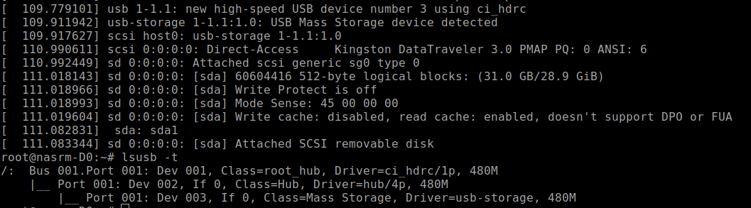
USB finally works. Now I’m able to connect an external USB hub to the socket and plug in thumb drives and USB hard disks. All works fine, except the USB-to-SATA converter, which is not soldered in yet. I saved that for the dessert, because I have other priorities.
This is the ‘lsusb -t’ picture of a thumb drive plugged into the USB socket.
NASR-M board bring-up, USB adventures
It’s USB show time! Xilinx documents suggest the USB3320 as a good USB PHY that works, and I’ve seen multiple development boards that use that chip. If it works for them, it will probably work for me, I thought. Despite being defined in Vivado hardware design, USB was not detected by the Linux kernel. Looking closely, I saw that a reference clock was ok, but there was no signal on the CLKOUT pin.
Petalinux Zynq configuration order
This is a short reminder to myself on how to configure the Petalinux for Zynq 7000.
First, source the settings.sh from the Petalinux root folder.
source ./settings.sh
Create the project from Vivado hardware definintion export. It's a good idea to provide a complete path to the xsa file.
    petalinux-create project --template zynq --name nasrm-usb
    cd nasrm-usb
    petalinux-config --get-hw-description /data2/hw/nasrm/usb_wrapper.xsa
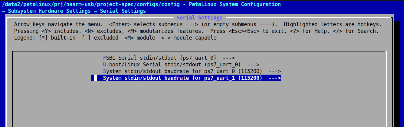
This will present a configuration screen. Don't forget to set the serial devices for boot messages and terminal access.
Then, configure the kernel with all of the necessary modules. Basically it's a good old linux menuconfig.
petalinux-config -c kernel
If the tinfo5 library is not found in ubuntu 24, you may symlink it somewhere or download from ubuntu 22:
    sudo apt update
    wget http://security.ubuntu.com/ubuntu/pool/universe/n/ncurses/libtinfo5_6.3-2ubuntu0.1_amd64.deb
    sudo apt install ./libtinfo5_6.3-2ubuntu0.1_amd64.deb
NASR-M board bring-up, first Linux boot
Today I was happily observing Linux boot messages on a NASR-M tty console. It was a major milestone in development. I decided to generate the PetaLinux image using the traditional workflow and leave the Yocto exploration for later. Sadly, good old PetaLinux tools will be deprecated in favor of Yocto in 2026.
NASR-M board bring-up, DDR3 test
Today is an important milestone in a board bring-up, as the DDR3 subsystem appears functional. I was able to run a Vivado bundled Zynq bare-metal DDR test with no errors. The test image was uploaded via JTAG and executed on a CPU core.
That was the most important indication of a system's health to me. Even if other subsystems don’t work properly, I’ll be able to respin the board with minimal effort. There are a few things to improve. Most importantly, the data strobe line length. Currently, the propagation delay between the strobe and data lines is very short, less than 0.01 nanoseconds. I suppose that contributed to somewhat narrow write eye width.
But hey, 65-71% is still ok, and definitely acceptable for a first prototype. Even without post-routing simulations, I’ve got a nice result. This routing won’t win the beauty contest, but at least it works, and someone may find it useful. Learn from my mistakes, kids :)
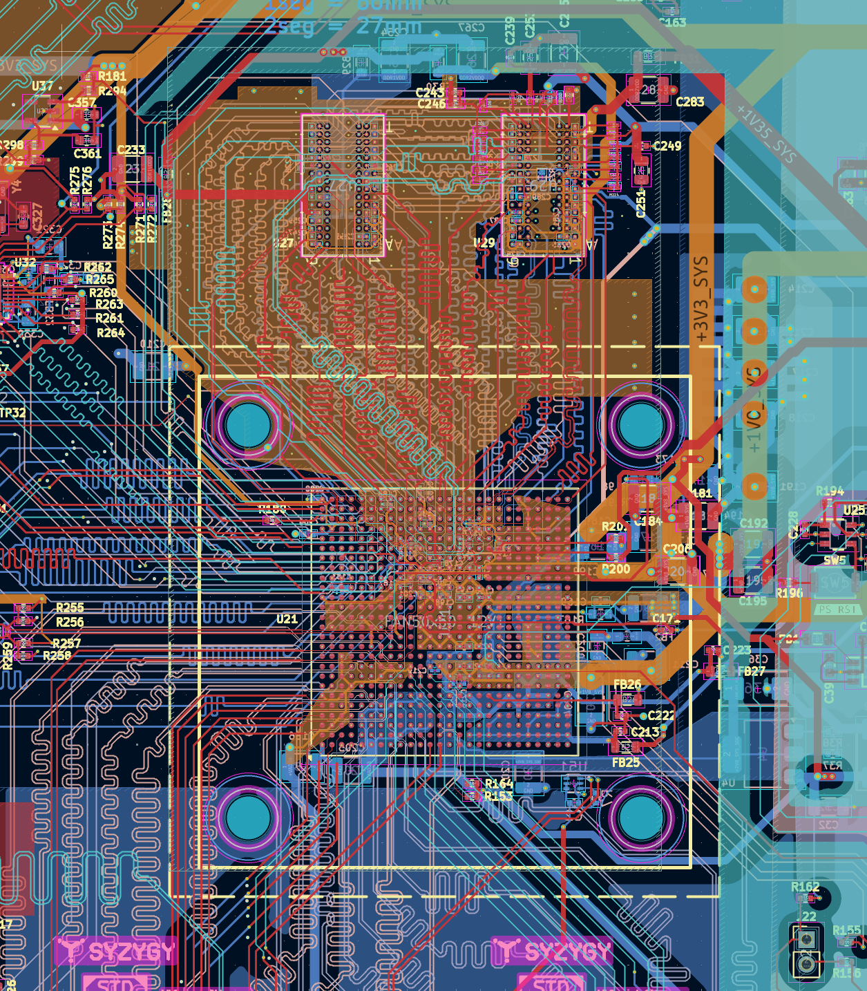
I’ve seen a lot of requests on the forums regarding fly-by topology applied to Zynq 7000, so here are a few tips and rules of thumb that worked for me:
NASR-M board bring-up, first JTAG connection
We’ve got a JTAG connection, ladies and gentlemen. My cheap Xilinx platform cable I ordered from AliExpress actually worked. I’ve got two of them. The first one didn’t work well and was pulling down the 3V3 power supply low, but the second one - bingo! The next step is a bare-metal CPU test.
Lessons learned: before succumbing to despair and unmotivated aggression, check the bootstrap pins and set them to JTAG Boot Mode (MIO[5 - 3] = 0, 0, 0), and don’t ever forget to set the MIO2 to 0 - Cascade mode.
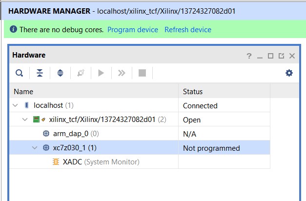
UPDATE If you are using Vivadio in GNU/Linux, make sure that Xilinx platform cable drivers are installed and udev permissions are set. Xilinx provides an easy way:
    cd Xilinx/Vivado/2023.2/data/xicom/cable_drivers/lin64/install_script/install_drivers
    sudo ./install_drivers