NASR-M board bring-up, USB adventures II
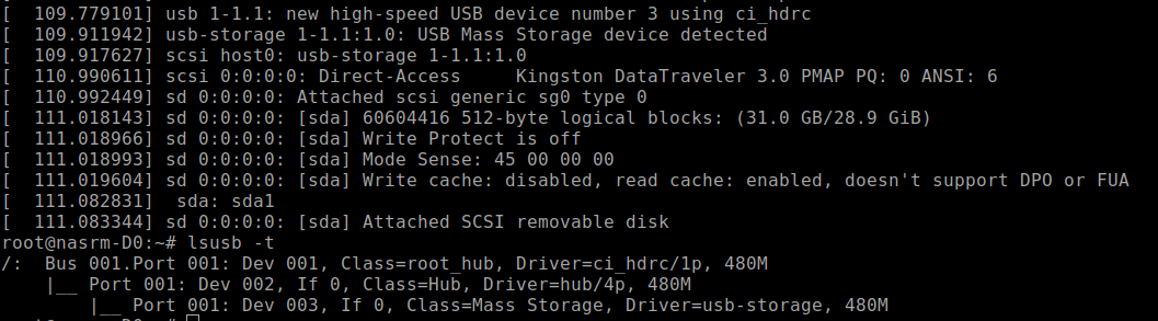
USB finally works. Now I’m able to connect an external USB hub to the socket and plug in thumb drives and USB hard disks. All works fine, except the USB-to-SATA converter, which is not soldered in yet. I saved that for the dessert, because I have other priorities.
This is the ‘lsusb -t’ picture of a thumb drive plugged into the USB socket.
NASR-M board bring-up, USB adventures
It’s USB show time! Xilinx documents suggest the USB3320 as a good USB PHY that works, and I’ve seen multiple development boards that use that chip. If it works for them, it will probably work for me, I thought. Despite being defined in Vivado hardware design, USB was not detected by the Linux kernel. Looking closely, I saw that a reference clock was ok, but there was no signal on the CLKOUT pin.
Petalinux Zynq configuration order
This is a short reminder to myself on how to configure the Petalinux for Zynq 7000.
First, source the settings.sh from the Petalinux root folder.
source ./settings.sh
Create the project from Vivado hardware definintion export. It's a good idea to provide a complete path to the xsa file.
petalinux-create project --template zynq --name nasrm-usb
cd nasrm-usb
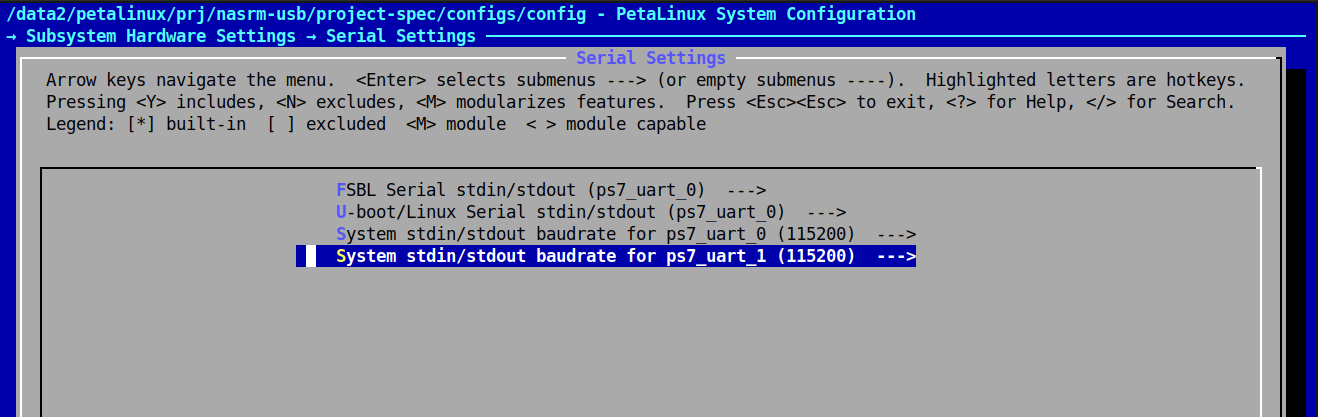
petalinux-config --get-hw-description /data2/hw/nasrm/usb_wrapper.xsa
This will present a configuration screen. Don't forget to set the serial devices for boot messages and terminal access.
Then, configure the kernel with all of the necessary modules. Basically it's a good old linux menuconfig.
petalinux-config -c kernel
If the tinfo5 library is not found in ubuntu 24, you may symlink it somewhere or download from ubuntu 22:
    sudo apt update
    wget http://security.ubuntu.com/ubuntu/pool/universe/n/ncurses/libtinfo5_6.3-2ubuntu0.1_amd64.deb
    sudo apt install ./libtinfo5_6.3-2ubuntu0.1_amd64.deb
NASR-M board bring-up, first Linux boot
Today I was happily observing Linux boot messages on a NASR-M tty console. It was a major milestone in development. I decided to generate the PetaLinux image using the traditional workflow and leave the Yocto exploration for later. Sadly, good old PetaLinux tools will be deprecated in favor of Yocto in 2026.
NASR-M board bring-up, DDR3 test
Today is an important milestone in a board bring-up, as the DDR3 subsystem appears functional. I was able to run a Vivado bundled Zynq bare-metal DDR test with no errors. The test image was uploaded via JTAG and executed on a CPU core.
That was the most important indication of a system's health to me. Even if other subsystems don’t work properly, I’ll be able to respin the board with minimal effort. There are a few things to improve. Most importantly, the data strobe line length. Currently, the propagation delay between the strobe and data lines is very short, less than 0.01 nanoseconds. I suppose that contributed to somewhat narrow write eye width.
But hey, 65-71% is still ok, and definitely acceptable for a first prototype. Even without post-routing simulations, I’ve got a nice result. This routing won’t win the beauty contest, but at least it works, and someone may find it useful. Learn from my mistakes, kids :)
I’ve seen a lot of requests on the forums regarding fly-by topology applied to Zynq 7000, so here are a few tips and rules of thumb that worked for me:
NASR-M board bring-up, first JTAG connection
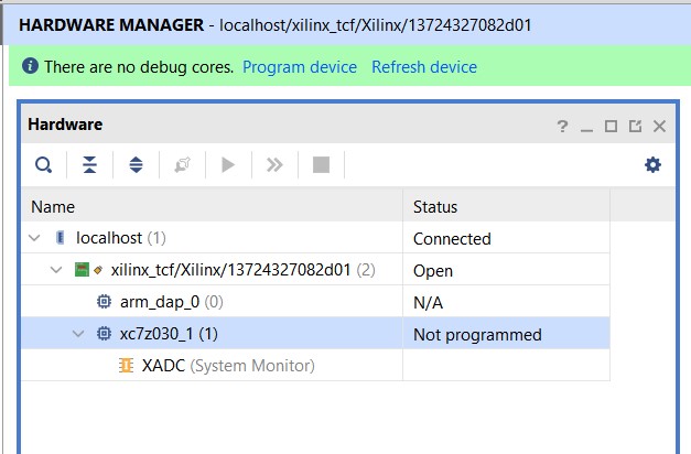
We’ve got a JTAG connection, ladies and gentlemen. My cheap Xilinx platform cable I ordered from AliExpress actually worked. I’ve got two of them. The first one didn’t work well and was pulling down the 3V3 power supply low, but the second one - bingo! The next step is a bare-metal CPU test.
Lessons learned: before succumbing to despair and unmotivated aggression, check the bootstrap pins and set them to JTAG Boot Mode (MIO[5 - 3] = 0, 0, 0), and don’t ever forget to set the MIO2 to 0 - Cascade mode.
UPDATE If you are using Vivadio in GNU/Linux, make sure that Xilinx platform cable drivers are installed and udev permissions are set. Xilinx provides an easy way:
    cd Xilinx/Vivado/2023.2/data/xicom/cable_drivers/lin64/install_script/install_drivers
    sudo ./install_drivers
NASR-M board bring-up, LMK03328 clock Zephyr OS driver
The LMK03328 clock driver is finally functional. Today, I was happily observing a sine-like signal at 33.33 MHz on the screen of my good old scope. I suppose it’s really a meander. Once I get a faster oscilloscope, I’ll be able to tell with confidence. What disappointed me was the low amplitude. The peak value was around 1.76 - 1.8V despite the 3.3V at the line #3 IO supply. The datasheet of LMK03328 states the following: “The 1.8-V LVCMOS driver supports rail-to-rail output swing only when powered from VDDO = 1.8 V +/- 5% (recommended VDDO for use with LVCMOS output format). VOH level is NOT rail-to-rail for VDDO = 2.5 V or 3.3 V due to the dropout voltage of the output channel’s internal LDO regulator.”
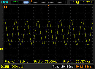
My expectation for peak amplitude was 2V or a little more. Let’s hope it's enough to clock the SOC. The driver for Zephyr OS is in a NASR-M-ZFW source tree. It’s a really simple one. First, it reads the register values described in a DTS, and then transfers them via the I2C. It works for me, and frankly speaking, I don’t want to spend any more time on this. At first, I tried to transfer the entire register config generated by TICS Pro, but that didn’t work. After a few tries, I had to cut out all register definitions that weren't related to the PLL or outputs, and it finally worked as expected.
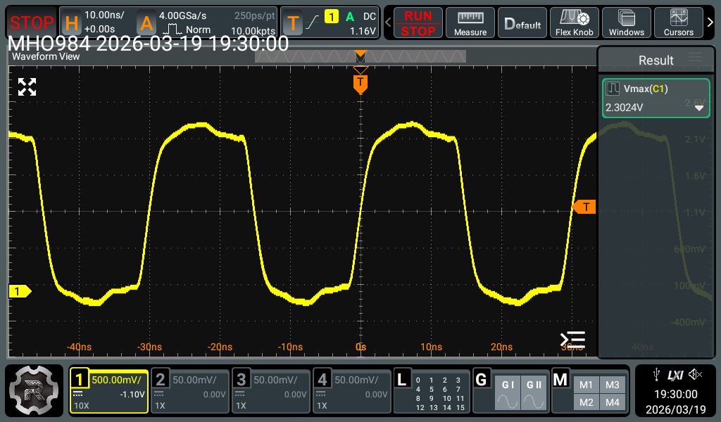
Update The clock signal amplitude is ok. My oldie scope was not able to display the fast rising signal correctly. Here is the oscillogram made with a faster scope.
Here is a DTS example:
NASR-M board bring-up, TCXO adventures II
Yesterday’s TCXO drama was resolved in a more elegant way than surgery. I have always been a fan of conservative treatment, and decided to try one last option before attempting rework. That option was an AC termination of the TCXO’s signal. The datasheet doesn’t explicitly mention single-ended AC termination of the reference input, so it’s kind of a gray area, but it’s perfectly fine for bootstrapping the board. Long story short, I replaced the termination resistor R127 with a 1uF capacitor, and LMK03328 magically passed my reference signal to the output. This might not be the optimal solution in terms of stability, phase noise, e.t.c, but it kind of works for now. In the next board revision, I’ll reserve another footprint for a TCXO with a CMOS output and then compare which one performs better. I’m rooting for an existing clipped sine wave TCXO because of fast rise and fall times, but let’s see. Now I have to work on the Zephyr driver for LMK03328 to correctly configure all the dividers and multipliers for proper PLL operation. This may take some time... Schema with correction is under the cut.
NASR-M board bring-up, TCXO adventures
People who have never done a board bring-up would not understand the adrenaline rush of finding yet another bug. It’s a wild ride, just like an extreme sport. Despite your butt being glued to the chair, you get a kick just before pressing the power button on a freshly assembled circuit or when the device is finally doing what it’s supposed to do, responding perfectly to I2C control. Fasten your antistatic wrist bands, ladies and gentlemen. Our next adventure is TCXO.
NASR-M board bring-up, Zephyr driver for TCA6416 GPIO
My love for Zephyr OS grew bigger after the successful driver adventure. A few days ago, I realized that the TCA6416 I2C GPIO expander isn’t supported by Zephyr, which was a setback. The TCA6416 GPIO controls the PLL clock on the NASR-M board. I need it to configure the clock. The good news was that Zephyr supports its bigger brother, TCA6424, which has 3 GPIO cells and 24 IO’s.
STM32Cube, STM32F401RE; USB host VBUS and UART1 conflict
Spent a significant amount of time trying to figure out why the USB host generated by STM32Cube was halting on STM32F401RE when UART1 was receiving data. It was driving me mad during the last couple of days. The board I'm using got no dedicated VBUS signal controlling the power on a USB interface, so I was assuming it's safe not to configure DriveVBUSFS in STM32Cube -> Middleware -> USB_HOST -> Platform Settings. I was spectacularly wrong. Despite UART1 RX being configured on PA9 pin (which is VBUS by default on STM32F401RE), it was still affecting the USB, so every incoming UART1 transmission was disrupting the USB host.
Qt5 cross-compilation environment for Raspberry Pi
This post is a brief extract of a wonderfully detailed video made by Ulas Dikme. Many thanks to Ulas for sharing his experiences, it saved me several days of work setting up the cross-compilation environment.
Ulas was using an Ubuntu 20 Virtual Box machine for building a sysroot and qt base. While it's not the best solution performance-wise, it's certainly very convenient in terms of being portable across the host machines. My Qt5 build system resides on a USB hard drive.